Check or non-return valves are a main item in process engineer’s design tool box to conquer reverse flow where this unfavorable deviation deems probable. Protection of sensitive equipment against possible damage or contamination, holding of the fluid in the system, prevention of crossover flow in systems with unequal line pressures and ensuring unidirectional flow in complex systems are among the applications of check valves.
There are certain types of check valves, each with their unique characteristics regarding the cost, head loss, laying length, special flow characteristics like waterway design for fluids containing solids, and slamming behavior. Since the focus of current article is on this last item, let’s have a quick look on the phenomenon of valve slamming.
Check valve slam occurs after flow stoppage (e.g. after a pump trips or a valve closes) when the forward flow reverses and flows back toward the higher-pressure source. The reverse flow is stopped almost instantaneously by the closing check valve, sometimes causing extensive pressure peaks, unbalanced forces and a loud noise. The phenomenon is not the impact of the valve disk re-seating but rather the rapid stretching of the piping system.
To prevent check valve slam, a check valve must either close very rapidly before appreciable reverse flow occurs or very slowly once reverse flow has developed.
In order to close rapidly, studies ref [1] indicate that:
- the disc should have low inertia and friction,
- the travel of the disc should be short, or
- the motion should be assisted with springs.
To close slowly, a check valve needs to be equipped with external devices such as oil dashpots and the pumping facility be capable of reverse flow and backspin. Such devices have proven effective performance in slow closure but add significantly to the valve cost and may cause clogging in dirty services. Herein, we use the term “basic” to refer to a check valve without oil dashpots and other devices that significantly slow down the closure of the valve and intentionally allow reverse flow to pass through it.
In severe applications, almost all basic check valves slam and in extremely mild applications, hardly any check valve will slam. The graphs presented in figure (1), are the test results of a series of experiments on different basic check valves in a horizontal piping run in water service and subjected to different initial forward flows and varying rates of flow reversals. The results clearly show the discrete behavior of check valves. Valves generally referred to as non-slam check valves such as NOZZLE or SURGEBUSTER check valves lay mostly in green zone compared to valves like BALL or SWING check valves laying mostly in the red zone. But the tricky part is that for high deceleration rates even a valve such as SURGEBUSTER enters the red zone. Similarly, a BALL check valves remains in the green zone at mild declarations. The slamming behavior of the check valve is thus a function of fluid system dynamics as well!
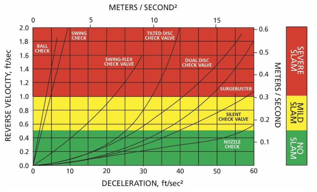
FIG 1 – Dynamic Characteristics of Various Check Valves ref [3]
The answer to preventing check valve slam is not to find the fastest closing check valve and make it the “standard”. Every check valve has inherent advantages such as low cost, low head loss, or special flow characteristics. The best check valve is not necessarily the one with the least potential to slam. For a low head application with a long pipe length, there is less potential for rapid flow reversal and the simplest and lowest cost check valve may be used without slamming. On the other hand, a multiple‐pump station sending water to a high head system with a nearby elevated or pneumatic surge tank will experience an extremely rapid flow reversal and only certain check valves can be used without slamming ref [2].
It is the responsibility of the valve manufacturer to provide the dynamic characteristics of their valves so that the process engineer can predict the maximum reverse velocity that may occur. It is suggested that for each type of check valve, a response curve should be generated to show the relationship between the deceleration of the liquid column and the maximum reverse velocity through the check valve ref [4].
It is crucially important to note the limitations of general response curves. For example, the test data may be based on a horizontal configuration. While some valves rely on gravity to accelerate disc closure such as the SWING and TD (tilted disk) check valves, installation in a vertical configuration, may have a great impact on their tendency to slam. Dynamic characteristics of the valve are dependent on valve size as well. Larger valves have heavier discs and longer strokes and will likely produce somewhat higher reverse velocities than predicted in general response curves.
Conclusively, valve specific response curve should be attained from the manufacturer for each application to make sure of the valve type selection.
References:
[1] Thorley, A.R.D. (1991). “Fluid Transients in Pipeline Systems” D&L George Ltd., Hadley Wood, England
[2] Ballun, John V., “A Methodology for Predicting Check Valve Slam”, Journal AWWA, Vol.99, No. 3, pp. 60-65, 2007.
[3] Val‐Matic Valve & Mfg. Corp., “Dynamic Characteristics of Check Valves”, White Paper, VM‐DCCV/WP, 2018
[4] Provoost, G.A., (1983). “A critical analysis to determine dynamic characteristics of non‐return valves, Proceedings of the 4th International Conference on Pressure Surges, Bath England, 275‐286.